Deduction of Ohm’s Law
We know that the relation between drift speed and electric current is
`I = n A e v_d`
`frac{I}{A} = n e v_d`
` J = n e v_d`
Where J is the current density.
Also,
`v_d = frac{e tau}{m}E`
Substituting the value of `v_d` in the above equation,
` J = n e frac{e tau}{m} E`
` J = frac{n e^2 tau}{m} E`
Here, m and e are constant, while n and `tau` are the characteristics of the conductor.
For a homogeneous conductor, frac{n e^2 tau}{m} ` is constant. It is called the conductivity `sigma` of the material.
Thus,
` J = sigma E`
In vector form,
` vec J = sigma vec E`
This equation is the microscopic form or vector form of Ohm’s law.
Consider a conductor having a length of `l` and a cross-sectional area A.
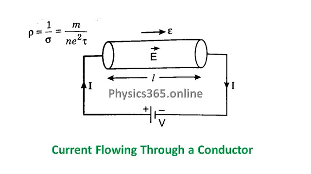
` J = sigma E`
Using,
`J = frac{I}{A}`
and
`E = frac{V}{l}`
we get,
` frac {I}{A} = sigma frac{V}{l}`
` V = frac{1 }{ sigma}frac {l}{A} I`
Since,
`rho = frac{1}{sigma}`
therefore,
` V = rho frac {l}{A} I`
` V = frac {rho l}{A} I`
But,
Hence,
This is Ohm’s law.
Where,
Where
Microscopic and Macroscopic Forms of Ohm’s Law
Microscopic form
`vecJ = sigma vec E`
Macroscopic form
`V = I R`
Limitations of Ohm’s Law
Non-Linear Devices
Semiconductors, diodes, and transistors do not strictly follow Ohm’s law. These devices exhibit non-linear behavior and are called non-ohmic devices. The graph between voltage (V) and current (I) is not a straight line.
Heating effect due to High Current
Temperature-Dependent Resistance
Ohm’s law is not applicable at very high temperatures because the resistance of a conductor changes with temperature.
Applications of Ohm’s Law in Electrical Circuits
Series Circuits
In a series combination of resistors, the current remains the same through each component, while the voltage is distributed among them.
Parallel Circuits
In a parallel combination of resistors, the voltage remains the same through each component, while the current is distributed among them.
Mixed Circuits
In a series-parallel mixed combination of resistors, Ohm’s law is used to find branch currents, total resistance, and voltage drops.
Conditions for Ohm’s Law to be Valid
- The temperature should remain constant
- Physical dimensions should not change
- Applicable only for Ohmic materials
- Constant Physical State
Other Applications
V-I Graph of Ohmic and Non-Ohmic Conductors
- Straight line for ohmic conductors
- Curved graph for non-omic devices
Ohm’s Law Solved Example
The resistance of an electric coil is 60 Ω, and a current of 3.2 A flows through it. Find the potential difference between two points.
Solution
Using Ohm’s law,
`V = R I`
`V = 60 times 3.2`
`V = 192 V`
Hence, the voltage across the coil is 192 V.